Recent Results
from the Princeton Gasdynamics Lab
Transition control at Mach 8 by helium gas injection Double cone flowfields at Mach 8
Turbulent boundary layer at Mach 8
Flowfield over a 4:1 elliptic cone at Mach 8
Transition on a flat plate at Mach 2.9
Turbulence measurements in Superpipe
Transition control at Mach 8 by helium gas injection
Mike EtzWe have found that low levels of helium injection near the leading edge stabilizes the turbulent boundary layer, apparently causing a reverse transition to laminar flow to take place. These results have important implications for thermal insulation of hypersonic engine surfaces, controlling mixing at high Mach number and influencing shock structure in shock-wave boundary layer interactions.
Using our new hypersonic facility, we have made preliminary studies of the injection of helium into a flat plate boundary layer over a range of Reynolds numbers. Figure 1 illustrates very recent experiments at Princeton in which we have demonstrated that helium injection into a transitional boundary layer delays transition indefinitely, apparently by lowering the Reynolds number in the near-wall region and cutting off turbulent production.
 |
Figure 1. Filtered Rayleigh images of boundary layers at Mach 8. The flow is from left to right. The top image is air, with no injection, at a Reynolds number based on momentum thickness of about 3,600. Bottom image is with helium injection near the leading edge. |
Figure 1a shows a CO2 enhanced scattering image obtained 432mm from the leading edge of a flat plate model in a Mach 8 flow. The boundary layer is turbulent, with a Reynolds number based on momentum thickness Req = 3200. Figure 1b shows images obtained at the same location but with helium injected into the boundary layer at a location 87mm from the leading edge and at a temperature which matches the wall recovery temperature. The dramatic difference due to the helium injection is clearly evident. Interestingly, injection of air at the same location with the same momentum flow rate has no significant effects, and it produces boundary layer images similar to those shown in Figure 1a. While the phenomenon illustrated if Figure 1b is far from understood, it appears that the injection of helium effectively reduces the Reynolds number near the wall (the kinematic viscosity of helium is a factor of 8 higher than that of air at the same temperature). Transition is delayed, and no turbulent mixing takes place. Surveys show that the low density region remains trapped near the wall (see Figure 2), apparently because mixing has been inhibited.
 |
Figure 2. Total temperature profiles at the x-location corresponding to Figure 1. |
A key question is how long this effect will persist downstream, and if a similar injection into a fully turbulent flow will cause reverse transition to a more laminar-like state. The phenomenon has important implications for heat transfer to the wall from the external flow: if the wall region is effectively laminar, the wall will be insulated to a much greater extent than if the flow is turbulent.
Return to top.
Double cone flowfields at Mach 8
Tom Magruder
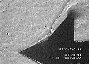 |
Figure 1. Schlieren images of flowfield over a double 25/50 degree circular cone at Mach 8. The flow is from left to right. |
The above schlieren image shows a Type V shock interaction on an axisymmetric 25/50 double cone. The flow conditions are air at Mach 8, Po=500 psi, To =775 K. Note that the large corner separation region significantly effects the flowfield, indicating the importance of viscous effects in this case.
Return to top.
Turbulent boundary layer at Mach 8
Mark Baumgartner
 |
Figure 1. On the left, filtered Rayleigh side-view images of boundary layers at Mach 8. The flow is from left to right. The Reynolds number based on momentum thickness is about 3,600. On the right, side-view images of dye in a boundary layer in water flow at zero Mach number. The Reynolds number based on momentum thickness is about 700. |
 |
Figure 2. On the left, filtered Rayleigh plan-view images of boundary layers at Mach 8. The flow is from left to right. The Reynolds number based on momentum thickness is about 3,600. On the right, plan-view images of dye in a boundary layer in water flow at zero Mach number. The Reynolds number based on momentum thickness is about 700. |
Return to top.
Flowfield over a 4:1 elliptic cone at Mach 8
Mark Huntley
| Figure 1. Pulse-burst motion picture (28 images at 500 kHz) of transition on the top face of a 4:1 elliptic cone at Mach 8. |
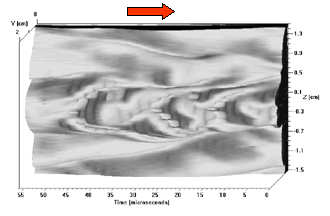 |
Figure 2. 3D visualization of transition on a 4:1 elliptic cone at Mach 8. |
More images of the elliptic cone.
Return to top.
Transition on a flat plate at Mach 2.9
Paolo_Graziosi
| Figure 1. Preliminary results on the transition of flat plate boundary layers at Mach 2.9. |
Return to top.
Turbulence measurements in Superpipe
Mark Huntley
| Figure 1. Preliminary results from turbulence measurements in Superpipe. |
Return to top.

This page last updated on October, 1999.