Introduction

The E. Howard Model 1 tower clock is a mechanical pendulum clock characterized by five mechanical systems. The first requirement is a motive force, which in this case is comprised of weights that rotate the main barrel, but is sometimes comprised of a mainspring. The gear train then increases the rotational speed and decreases the rotational torque in order to drive the pendulum. The escapement wheel controls the transfer of the potential energy stored in the weight system and transferred by the gear train to the pendulum in precisely timed intervals. The pendulum provides the precise time intervals isochronously (frequency independent of amplitude). Lastly, the indicator, comprised of the clock face and hands, records how often the escapement has rotated.


Weights and Winding Mechanism

The simplest system consists of a weight hung on a cord wound around the main barrel. In order to make the necessary winding less frequent, pulleys are often added. Each pulley allows the weight to travel half as fast as the cord, so that with only a few pulleys the winding interval can be drastically reduced. The tradeoff is increases friction with each pulley. However, this additional friction only becomes a problem if the pulleys are not maintained. We have not yet completed the pulley system on the Howard clock, which will depend on the clockĄ¯s situation in the clocktower in Trenton. However, we expect to have a drop of 6-8 feet in order to accommodate the 9 foot pendulum. We will maximize the winding interval with 2-4 pulleys.

One problem that could arise with weight driven clocks is that during winding all the gears are turned backward (causing excessive wear) and therefore the clock hands must be repositioned with each winding. The Howard clock includes a winding mechanism which precludes both these issues. To allow the clock to be rewound without turning all the wheels backward, the first wheel on the gear train (called the great wheel) is not fixed to the barrel, but rather rides loose on the barrel arbor. A click on the wheel works on ratchet teeth cut on the barrel, thereby allowing the barrel to turn the wheel and therefore the gear train while the clock is operating normally. When the barrel is turned the other way for winding, however, the wheel is free to remain stationary. This saves all the gears from the extra wear that would result from winding backward, but the clock would continue to lose time while it was being wound.


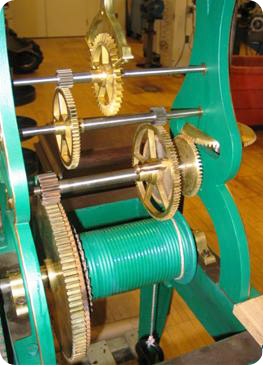
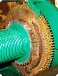
Figure 1: winding mechanism

Great wheel, gear on right with large teeth; main barrel, left; ratchet wheel, between

To prevent the clock from stopping or running backward while winding, Harrison invented the maintaining power mechanism. In this system, the winding click is not on the great wheel, but on a ratchet wheel placed between the great wheel and the barrel, with the teeth facing the opposite direction from the ratchet on the barrel itself. The rotation of the barrel then drives this intermediate ratchet wheel, which drives the great wheel through an internal spring. This circular spring in the Howard clock is inside the great wheel, with one end attached to the ratchet wheel and the other to the great wheel. The ratchet wheel, being driven forward by the barrel and the weight, continually stresses the spring, thereby urging the great wheel forward. During winding, while the drive from the barrel is absent, the ratchet wheel is held from turning backward by a click attached to the clock frame, and the spring continues to turn the great wheel and the gear train. Through this ingenious mechanism, the clock automatically continues to keep time even during the winding operation.


Figure 2: gear

Conversely to gear trains in automobiles, where a small gear drives a larger gear in order to reduce the speed and increase the torque, the gear trains in clocks start with a rather large gear and transfer energy to smaller gears. In this way, the low-speed, high-torque power of the main barrel is translated into the high-speed, low-torque power of the escape wheel. Some of the earliest clocks had a velocity multiplication of 480. In other words, a main barrel that rotated once every eight hours turned an escape wheel that rotated once every minute. Through the reduction of torque through the gear train, the clock maintains the potential energy in the weight system while using very small amounts of kinetic energy, thereby allowing the clock to run for an extended period without winding.


One of the more interesting aspects of the Howard gear train is the shape of the gear teeth. The requirements for a long-lasting, quiet, and low-friction gear system are as follows:

1. A constant velocity ratio
2. Tooth shape easily producible with mathematical accuracy
3. Each wheel interchangeable with any other gear of the same pitch
4. Tolerance for small changes in the depth of tooth engagement
5. Strong tooth shape with little radial thrust


Figure 3: involute teeth and tangent line (red)
http://www.mech.uwa.edu.au/DANotes/gears/meshing/meshing.html

Figure 4: Howard involute teeth

Gears with teeth shaped like the involute of a circle approach these ideal conditions (the involute of a circle is the curve traced by the end of a string as it unwinds from a stationary circle). As two involute gears engage, the radius of the contact point increases. In order to maintain a constant velocity ratio with a continually changing contact point diameter, the width of each tooth decreases towards its point (with an involute profile). As the point of contact of the two teeth moves away from one tooth and towards the other, it describes a straight line tangent to the base circles of both gears, thereby keeping the thrust at right angles to the contact faces. If the depth of tooth engagement changes slightly, as is likely as bearings wear, the only change is the slope of the tangent line between the two base circles. Therefore, the velocity ratio remains constant.


Pendulum

Early pendulum clocks, regulated by the crown escapement (a coarse device which consumed a large amount of power with significant friction), required large (~30°) swing amplitudes. This posed a problem in that for angles larger than 5-10°, pendulums are not isochronous. The invention of the anchor escapement in the 1760s (the Graham escapement is a type of anchor escapement), which interferes with the pendulum movement mush less and is subject to much less frictional force, allowed the use of small-amplitude isochronous pendulums, thereby solving the problem of obtaining equal-timed beats. The period for a small angle pendulum is given approximately by

where L is the pendulum length and g is the acceleration of gravity. If left to itself, the pendulum would obviously slow down and eventually stop due to friction. The escapement regulates the pendulum swing by providing an additional impulse on each swing. A more accurate approximation for a pendulum with friction is given below, where b measures the amount of friction:


Indicators and faces

The Howard clock will have three faces, each eight feet in diameter. Both the hour and minute hands of each face will be controlled by a single shaft running to the face, where a gearing mechanism translates the rotational motion of the shaft to the two different rotational speeds of the two hands. To avoid the necessity of aligning the clock perfectly with all three faces, the shafts will pass through a set of universal joints.

The Howard clock also includes a mechanism by which the clock hands can be easily adjusted. The gear on the arbor immediately above the main barrel can be disengaged from the drive system by pulling a pin, thereby allowing the hands to be moved independently from the main barrel.

Figure 5: hand setting mechanism


Written by Morgan Fowler '10


References
Denny, M. (2007). Ingenium: Five machines that changed the world. Baltimore: The Johns Hopkins University Press.
Rawlings, A. (1948). The Science of Clocks and Watches. New York: Pitman Publishing Corporation.
http://www.perpetualpc.net/clock_repair_essay.html
http://en.wikipedia.org/wiki/Pendulum_clock