Building Creation and Rendering
From Plan to Wireframe |
Material Preparation |
From Wireframe to Finished Model
From Plan to Wireframe
This document is a detailed description of the full process
employed to build an AutoCAD model of a building and then complete a
photo-realistic rendering of that building. For illustrative purposes,
images of the
Monastery of Constantine Lips
will be presented at various points throughout the document.
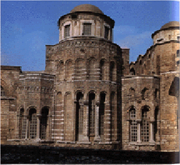
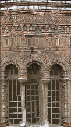
Lips Monastery
The first step in the creation of a completed building model is the
construction of a 3-d wireframe model using AutoCAD. For most of the
Byzantine structures still extant in modern Istanbul there are a variety
of bibliographical sources which contain, along with abundant historical
information,
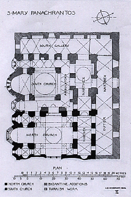
plans
and
elevations
of the structures in varying degrees of
detail. In the case of the
current project, these drawings were supplemented by measurements made in
the field during the spring of 1995.
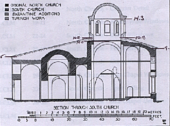 Measured Drawings
There are various methods of constructing models in Autocad. We have
found that the easiest and most applicable method employs the solid
modeler included with AutoCAD Release13 (known previously as the AME
solid modeler). This method utilizes the boolean operations
subtraction and union. Using simple 3d objects such as boxes, cylinders
and spheres, more complex
domes,
vaults,
and windows can be created.
With those three elements, along with standard straight wall, floor, roof
sections, and columns (AutoCAD cylinders) almost all of the
structures being studied can be accurately modeled.
There is also a question as to what degree of detail is necessary in the
model, and what can be left up to the capabilities of the texture mapping
software. We feel that much of the detail work is easier to achieve
using texture
mapping rather than creating excessively complex AutoCAD models. Clearly,
all vaulting, domes, walls, etc must be modeled
accurately. It is probably unnecessary, however, to model objects such as
column
capitals and relief work. For the most part we have found that a great
deal of detail can be added to a model through the use of well conceived
and executed photographs in the texture mapping process.
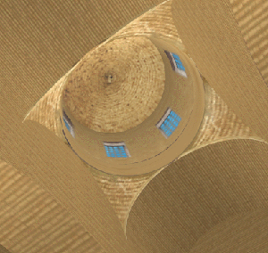
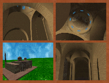
At the completion of this stage, the entire geometry of the building has
been laid out. AutoCAD provides the ability to view this model from
various angles, with hidden geometry, and a rough rendering, without
texture maps.
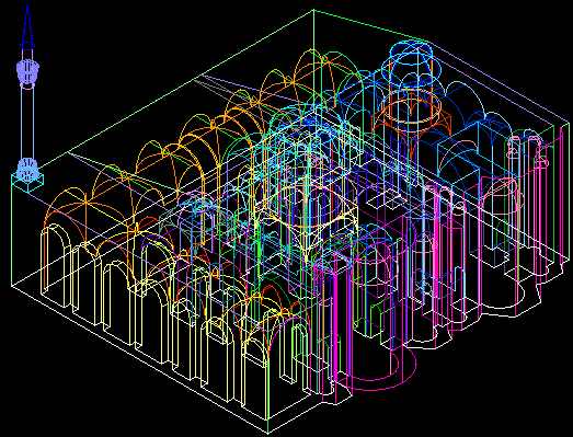
Completed AutoCAD
Model
Material Preparation
This is perhaps the most critical stage in the journey towards a
photorealistic rendering. In order to create a convincing effect on the
finished model, materials must be prepared from photographs in such a
manner as to make mapping possible.
The first step in this stage is the actual taking of photographs. This
is critical, for without consistent, perspectiveless photos, materials
cannot be made convincing. For large expanses of wall and roof, we
have found the most effective method involves repeating (in a tiled
pattern) a relatively
small photographic sample of the brickwork in order to fill the
large area.
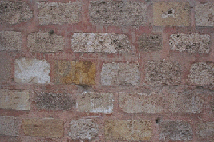
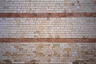
Sample Brick Photos
This can create a very convincing effect, but is highly
dependent upon the quality of the photos. The photo must be taken
directly facing the wall, with a a lens that will not create any wide
angle distortion, and with as even lighting as possible. These
requirements ensure that there will be no patterning of angle, or light
and dark within the sample that will become obvious when the pattern is
repeated to fill a wall.
As stated earlier, a relatively low degree of detail need be included in
the AutoCAD model, and a great deal of "apparent" detail can be added by
appropriate use of photographs. For example, effects such as windows
with
mullions and transparent panes
can be achieved. Additionally, the
trim around windows
can be effected by use of an
overview photo, rather than actual modeling.
After all materials have been prepared, the wireframe model can be
imported to 3dStudio, and the texture mapping can begin.
From Wireframe to Finished Model
The final step and most exciting step towards a finished model is the
application of prepared photographic materials to the wireframe model.
This stage requires great familiarity with the materials editor of the
software package 3dStudio (an application which allows the photographs
prepared in the
previous step to be actually applied to the structure). The process is
immensely powerful and actually fairly simple to employ.
In the materials editor the photograph, prepared using Photoshop, is
specified as the texture map for a newly created material. In addition
to textures, photograph files can also be used as bump and opacity maps
to create the truly textured and transparent surfaces previously described.
In order to make an object actually appear mapped, two things must be
done to it. First, the prepared material must be assigned to the object.
Second, because the material has a pattern to it, coordinates must be
assigned to the object which specify in what orientation and at what
scale the photo is to be applied. By following these two steps,
photographs can essentially be "pasted" on to all of the walls, domes,
and vaults in the building. From the plans and elevations, we have
progressed to the point where exterior and interior views are possible,
and, if we have accomplished what we had hoped to, one feels as if he or
she is looking at a view of the actual structure.
Return to Home Page