Research: Thermally exfoliated graphite oxide: An alternative to CNTs
Ahmed Abdala, Douglas H. Adamson, Michael J. McAllister, David L. Milius, Margarita Herrera-Alonso
Advisors: Robert K. Prud'homme and Ilhan A. Aksay
Collaborators: L. Catherine Brinson, Rodney S. Ruoff, and SonBinh T. Nguyen, Northwestern University; Jun Liu, Sandia National Laboratories (now at Pacific Northwest National Laboratory)
The growing interest for research on carbon nanotubes (CNTs) is driven by their outstanding electronic, mechanical, and thermal properties [1]. Some of their emerging applications include their use as hydrogen-storage reservoirs [2], nanowires [3], superconductors [4], and nanocomposites [5]. Despite this, the elevated cost of production of CNTs has limited their use in large-scale applications. On the other hand, carbon nanotubes are described as rolled-up sheets of graphene, therefore graphene nanoplatelets (GNPs) should perform similarly to CNTs. The source for GNPs is graphite, an inexpensive, naturally abundant material with excellent properties: Young’s modulus = 1060 GPa, thermal conductivity ~2000 W/m-K, and electrical resistivity ~4 x 10⁻⁵ Ohm-cm[6]. Therefore the use of GNPs as a reinforcement material should produce low-density nanocomposites with high strength and toughness. Exfoliation of graphite down to individual graphene plates has been attempted with limited success [7]. Exfoliation, which generally proceeds via thermal or chemical treatments, has thus far resulted in expanded graphite with surface areas well below the theoretical value of ~2,700 m2/g. The highest surface area achieved is 555 m2/g [8]. In response to the evident interest in producing an economically-viable alternative to CNTs, we have developed a process that results in exfoliated graphite with surface areas as high as 1500 m2/g.
The process of exfoliation is based on the thorough intercalation/oxidation of graphite (H2SO4, HNO3, KClO3) followed by a thermal shock (Figure 1).
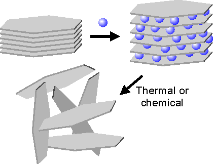
Figure 1: Schematic of the intercalation/exfoliation process
High-resolution transmission electron microscopy images of graphite and graphite oxide are presented in Figure 2 (A and B). While the layered structure of graphite persists after oxidation, the change in hybridization of the carbon atoms upon oxidation produces a wrinkled morphology. Rapid superheating of graphite oxide (~ 2000 ºC/min) results in a pressure buildup inside the intergallery spacing that can effectively separate graphite oxide to a graphitic material with no long-range order. HRTEM of TEGO (Figure 2, C) indicates that at the morphology at the edge is similar to that of graphite oxide, however in the bulk it appears to be amorphous. When dispersed in 1,2-dichlorbenzene, sonicated and deposited on mica, the thickness of the nanoplatelets is approximately 2 nm, as measured by AFM. The surface area measured by BET (Figure 2, graph) is sensitive to the exfoliation temperature and the processing conditions. The maximum surface area achieved was ~1500 m2/g.
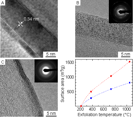
Figure 2: (A) HRTEM image of graphite showing its characteristic 0.34-nm interlaminar spacing. (B) HRTEM images illustrate the intercalation of GO samples oxidized for more than 96 h. The selected area electron diffraction (SAED) pattern in the inset contains information from many GO grains. A typical sharp, polycrystalline ring pattern is obtained. The first ring is attributed to the (1100) plane, and the second ring is to the (1120) plane. The bright diffraction spots corresponding to the (1100) reflections within the ring retain the hexagonal symmetry of the [0001] diffraction pattern. (C) HRTEM image of crumpled TEGO produced from a 96-h acid treatment. The selected area electron diffraction (SAED) in inset shows an amorphous structure. Graph, BET surface area measurements of TEGO with different processing conditions as functions of the exfoliation temperature.
PMMA nanocomposites with TEGO as the reinforcing material were prepared by solution-based processing methods and compared to single-wall carbon nanotubes (SWCNT) and expanded graphite (EG) nanocomposites. As observed in Figure 3, PMMA/TEGO nanocomposites outperformed the others. The data indicate that the improvement in mechanical properties is due to a superior dispersion of the TEGO nanoplatelets in the polymer matrix, enhanced by the interactions between the functional groups of the platelets and the polar functionality of PMMA.
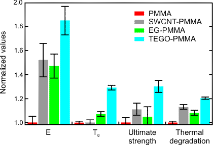
Figure 3: Summary of thermomechanical property improvements for 1 wt% TEGO-PMMA compared to SWCNT-PMMA and EG-PMMA composites. All property values are normalized to the values for neat PMMA and thus relative to unity on the scale above. Neat PMMA values are E = 2.1 GPa, Tg = 105 °C, US = 70 MPa, thermal degradation temperature = 185 °C.
For more information on this research topic, please contact Margarita Herrara-Alonso. Additional information concerning the CML can be found on our website.
References
1. P. M. Ajayan Chem. Rev. 99 1787 (1999)
2. A. C. Dillon, K. M. Jones, T. A. Bekkedahl, C. H. Kiang, D. S. Bethune, M. J. Heben Nature 386 377 (1997)
3. P. Ajayan, S. Iijima, Nature 361 333 (1993)
4. A. Kasumov, R. Deblock, M. Kociak, B. Reulet, H. Bouchiat, I. Khodos, Y. Gorbatov, V. Volkov, C. Journet, M. Burghard, Science 269 1550 (1999)
5. T. Ramanathan, F. T. Fisher, R. S. Ruoff, L. C. Brinson, Chem. Mater 17 1290 (2005)
6. B. T. Kelly in Physics of Graphite; Applied Science Publishers: Essex, U.K. (1981)
7. D. D. L. Chung J. Mater. Sci. 22 4190 (1987)
8. A. D. Lueking, L. Pan, D. L. Narayanan, C. E. B. Clifford J. Phys. Chem. B 109 12710 (2005)
![]()
![]()
![]() © 2006 Princeton University, Ceramic Materials Laboratory.All Rights Reserved.
© 2006 Princeton University, Ceramic Materials Laboratory.All Rights Reserved.