Pressure-Enthalpy
Diagram
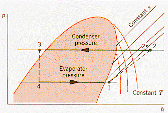
The pressure-enthalpy diagram opposite
is
for a typical refrigerant. The two-phase
zone is shaded orange,
and a typical cycle
is indicated with the numbers corresponding
to
those used in this experiment. Isotherms
in the vapor region (right of
the two phase zone)
are shown as orange arcs. In the two phase
zone,
isotherms and isobars coincide, and in
the saturated liquid region the isotherms
are vertical.

From: Moran & Shapiro, "Fundamentals of Engineering Thermodynamics," Wiley (1992)
The path (1- 2s) is for an ideal isentropic compressor, the path (1 - 2) is for a real compressor. The path (2 - 3) takes place in the condensing tank, and the path (4 - 1) is in the evaporating tank. Process (3 - 4) represents the expansion valve.