DO NOT INSERT DEVICE YET!
To use this page you must first create a file suitable for burning into your chip. For most chips we will create a *.hex file from running an *.asm file through the XASM assembler. The exception is the GAL16V8 which requires a JEDEC file. The procedures for this can be found at http://www.princeton.edu/~mae412.
Follow red instructions if you are using the 2532A.
Follow green instructions if you are using the 27C64.
Follow blue instructions if you are using the 28C64.
Follow purple instructions if you are using the GAL16V8.
Follow black instructions for all chips.
EMP-21 Programmer should automatically turn on when software is started, unlike the EMP-20 which has a switch in the back. There is a power light next to the ZIF socket (Zero Insertion Force) and the ZIFs handle should be straight up.
The power light has three colors:
GREEN for successful programming of a chip. Also the default color.
YELLOW for a burn in progress.
RED for a failure during programming. Light will cleared by the next successful programming.
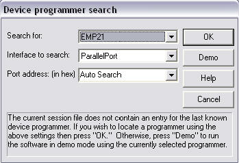
In the MAE412 folder double click the EMP21 shortcut or from the Start menu, go to All Programs >> nei >> EMP Device Programming Software.
When the Device programmer search screen appears, press the OK after you match the settings with the figure above.
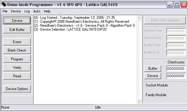
The
Programmer should now be displayed, click the
![]() button.
button.
After the software builds a devices list the Device Selection window should appear.
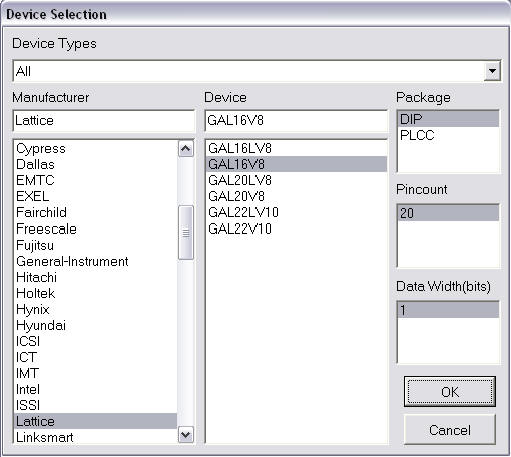
Please ensure that the Package selected is DIP (Dual In line Package). Pincount & Data Width(bits) will be selected automatically.
Under
Manufacturer click TI , then TAB over to Device and
select TMS2532A .
Under Manufacturer click
AMD, then TAB over to Device and select AM27C64 .
Under Manufacturer click
Atmel, then TAB over to Device and select AT28C64B .
Under Manufacturer click Lattice , then
TAB over to Device and select GAL16V8.
Press OK.
In the Programmer window, click on the ![]() button.
button.
In the Buffer Editor, we first need to fill the buffer so that all the
locations are at the same erased state as the chip that will be programmed. For our chips the erased value is 1111 1111 binary or FF hex. So a proper fill is done by pressing the
![]() button.
button.
Now it's
time to load your *.hex (*.jed) file. Press
the ![]() button and
navigate to your file.
button and
navigate to your file.
NOTE: on Windows 98 machines, your file should be under C:\My Documents\user.
Our XASM created file uses Intel Hex were as the file for the GAL16V8 needs JEDEC selected.
The Load file option window will appear.
Set the File range from 0000F000 to 0000FFFF, then press OK.
Set the File range from 0000E000 to 0000FFFF, then press OK.
Set the File range from 0000E000 to 0000FFFF, then press OK.
Set the Buffer range from 00000000 to 00000FFF, then press OK.
Set the Buffer range from 00000000 to 00001FFF, then press OK.
Set the Buffer range from 00000000 to 00001FFF, then press OK.
Now that your buffer is loaded, check the end of the buffer to see that the last four bytes are no longer FF.
This is your "reset vector".
Now you can close the Buffer Editor and return to the Programmer.
In the Programmer window, click on the![]() button only if you are using an UV erasable device (i.e. 2532A or
27C64). Electrically erasable devices will
"Patch" the new program over top the old one. UV erasable devices
can not be erased by the programmer. Therefore they have to be blank
before programming.
button only if you are using an UV erasable device (i.e. 2532A or
27C64). Electrically erasable devices will
"Patch" the new program over top the old one. UV erasable devices
can not be erased by the programmer. Therefore they have to be blank
before programming.
Now look at the Programmer window to see if the Family Module matches what is physically in the EMP-21. Now you can insert your chip into the ZIF socket, following the picture on the case.
You are ready to program. Press the
![]() button and wait for
the light to change from yellow to green. If the light changes to red,
then erase or replace the chip and try again.
button and wait for
the light to change from yellow to green. If the light changes to red,
then erase or replace the chip and try again.
If the default settings are in place the software should automatically verify that what is in the chip matches the buffer.
If it doesn't, press the
![]() button.
button.
Remove your chip. Programmer will automatically turn off when program is closed.