| |
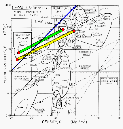
The diagram
illustrates how the shape factor, fB,
can be accounted for. Each shape for a given material can be treated
as a "new" material with a modulus E* = E/fB
and a density r* = r/fB.
The red dots on the diagram correspond to the material properties modified
by the shape factors shown in the boxes.
The green (E*/r*) = C curve shows the effect of shape change on the CFRP spar and the
yellow curve the effect of shape change on the Aluminum spar. The shapes
in both cases are self similar over the range of fB values shown. The CFRP zone lies above the aluminum alloy
zone and makes this a better material choice taking into account Young's modulus,
density, and a possible spar configuration. The blue line on the diagram
represents the selection criterion (E/r2)
= 10.
Materials that are above the line meet the criterion. |
|
|
|
|
|
|
|
|
|
|
|