The purpose of this project was to stand a pencil on its end using an electronic feedback circuit.
Why you ask?
We wanted to come up with an idea that demonstrated a useful physics principle in a cool but silly way.
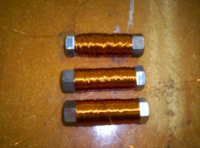
The lasers used were basic laser pointers using three 1.5 volt batteries. To disperse the small dot usually produced by the pointer into a beam wide enough for our project, we fitted a different end to it that produced a beam that was flat and narrow with a width of approximately 3 times the pencil's width at a distance of several centimeters. However, the problem with this beam is that as the batteries died, the power of the beam would gradually diminish, constantly forcing us to change the circuit's sensitivity, something that could clearly not go on. We therefore removed the batteries and using a soldering iron and several wires connected the laser pointer to a DC current source of 5 volts.
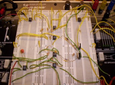
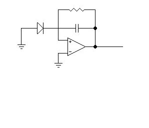
The second component is the feedback loop itself (above on right). This can be divided again into two segments. The first is a simple instrumentation
amplifier. This device outputs the difference between the two input voltages. Initially we had used an integrated circuit that amplified
this difference - but this proved to saturate the amplifier. So we replaced this component with a different amp with no gain. The reference
signal comes from a special chip that outputs a constat 10 volts. This was run through a potentiometer. By doing this we could artificially
adjust the zero point of the feedback - and move the pencil toward or away from the variable magnet.
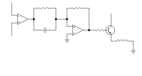
Next we had another op-amp configured slightly differently. This circuit amplifes the incoming voltage by a factor of Vout = Vin*R2/R1 where
R2 is the value of the resistor in the loop and R1 the resistor in the input. Were were to use just two resistors this would create feedback
proportional to the deviation of the pencil from the reference voltage. This proved very unstable - the magnets tended to overpower themselves.
The solution was to introduce differential feedback. The parallel R-C circuit accomplishes this. The impedence of the capacitor gets small when
oscillations are high frequency. This means that the overall resistence of the R-C circuit drops and the voltage is heavily amplified. When the oscillations
get smaller the resistence rises and the voltage is less heavily amplified. This turned out to be the key to our circuit.
Finally we ran the output from this amplifier to a transistor - this only gives a positive voltage and also allows us one final control over the level of the output.
They also have a tendency to burn out - justifying the cooling fan. The output from the transistor runs to the magnets.
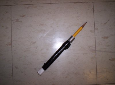
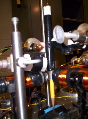
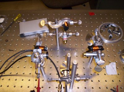
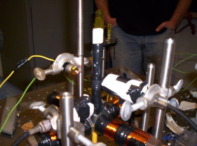
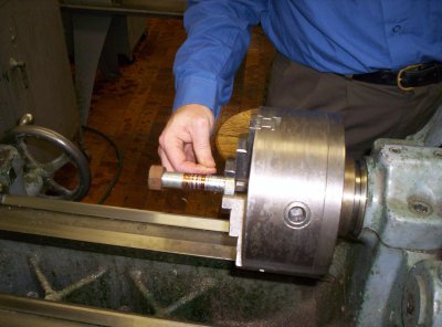
The other modification that we made to our pencil is the addition of the metallic ring around it at the level of the magnets in order to give them something to act on because we quickly discovered that the small piece of metal that holds the eraser onto the pencil is not magnetic. The level of the additional metallic strip was determined by the height of the magnets, whose height in turn was determined by the fact that we found some handy clips that worked perfectly in holding them. The magnets themselves also went through some development.
The magnets are hooked up perpendicular to each other so that the axes are independent from each other. We have one permanent magnet on each one, hooked up to their own individual adjustable power sources, and one variable magnet opposing it. The variable magnets are hooked up to the feedback loop circuit that was previously described. The result is that as the pencil moves away from a variable magnet the feedback circuit boosts the voltage to the magnet pulling the pencil back into place. Likewise as it moves towards the magnet the voltage drops allowing the permanent magnet to pull the pencil back away.
The construction of the device itself took us almost the entire time allotted to the project. There turned out to be several tricky problems inherent to the circuit that we had to work out. One was the transistors that we kept burning out - another was the tendency of wires to come unplugged or accidently cross and short circuit (usually killing a transistor in the process). The first big step came this Tuesday afternoon when we added the cardboard shield to keep the pencil from straying too far (Click image for video).
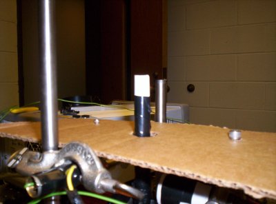
Clearly we were close - but it wasn't until the addition of the differential feedback early Tuesday evening that we found real success. Now the pencil tends to be completely stable with its center point adjustable through the potentiometers. The video we have here shows an oscillation the pencil picked up last night. We don't know what caused it - it could be the feedback overshooting or it could be a resonance in the circuit - but it clearly shows the stability of the fully balanced pencil (Click image for video).