Team Members (left to right):
Paul Nelson
Denis Erkal
Aaron Wertheimer
Ma'ayan Bresler
Professor Mike Romalis

|
Team Members (left to right): Paul Nelson Denis Erkal Aaron Wertheimer Ma'ayan Bresler Professor Mike Romalis
|
|
Objective: construct and fire a rail gun.
Definition: a linear electromagnetic accelerator consisting of two rails and an armature in which the large amounts of current are passed through the rails to accelerate the armature by a Lorenz force. Below is a schematic view of the rail gun from the top. (We created this awesome image ourselves! For permission to reproduce, please write a letter to one of the rail gun team member's attorneys.)
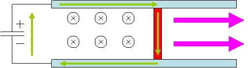
The green lines represent the current, the red bar represents the armature, and the cyan bars represent the rails. As the image shows, the current forms a magnetic field directed into the page. The current in the armature, in the presence of this magnetic field, is thereby pushed to the right [F = i ( l x B )].
Blueprint:
Dimensions:
We decided to make the rails 6 inches long and relatively thin, so that the
armature could have a "runway" along which to accelerate.
Power:
A rail gun uses a great deal of power. We considered two options:
- a steady power source, or
- charged capacitors.
Because rail guns do not require a long duration of power, we decided the
charged capacitor approach would be advantageous.
We used 12 capacitors each rated at 2000 microfarads each, charged up to 400
volts. for a total of 1920 joules. Online we found experimental evidence
predicted a efficiency percentage of roughly .1% which with our capacitors
would give our .2 gram armature a speed of 138 m/s (~300 mph). (Of course, we
did not expect to match this efficiency achieved by expert hobbyists).
With the constant power supply we had available, of 100 amps, we expected a
force of about .1 millinewtons (DO THE EQUATIONS OUT, so it looks
professional).
Armature options:
There are several constructions that would allow the armature to slide while
closing the current loop:
- simply place the armature on top of the rails
- cut a groove in the rails and rest the armature in it
We chose the latter approach to minimize abnormalities of the B-field due to end effects.
- choose a cylindrical or spherical armature to decrease friction
- choose a flat armature to increase surface contact and minimize electrical resistance, thus increasing the net current and the resulting Lorenz force, as well as decreasing heat production which might lead to the rails melting.
Again, we chose the second option.
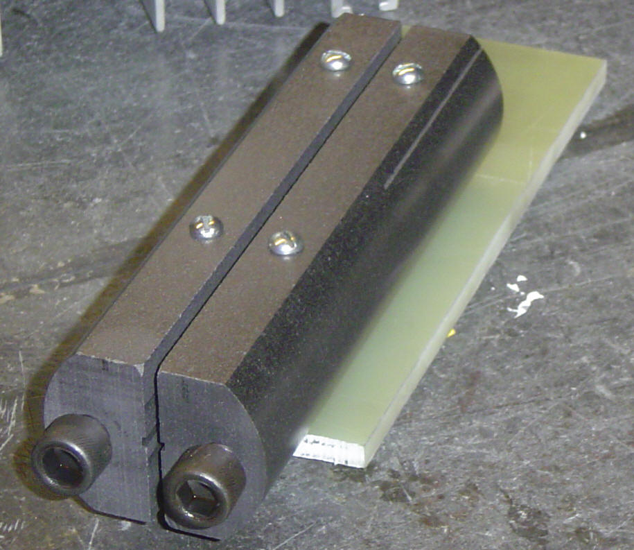
You can see the groove in our final product, in the middle between the two bars:

As you see the groove is flat, and we fired the gun using either a small graphite disk or brass nut which we slid into the groove.
- the last remaining design question is materials. Online we read that copper was the best material, with a silver coating, but we didn't have silver coating at our disposal and so discovered our own approach, further discussed under the procedure section.
Rail Building Procedure:
-Our first build used copper rails.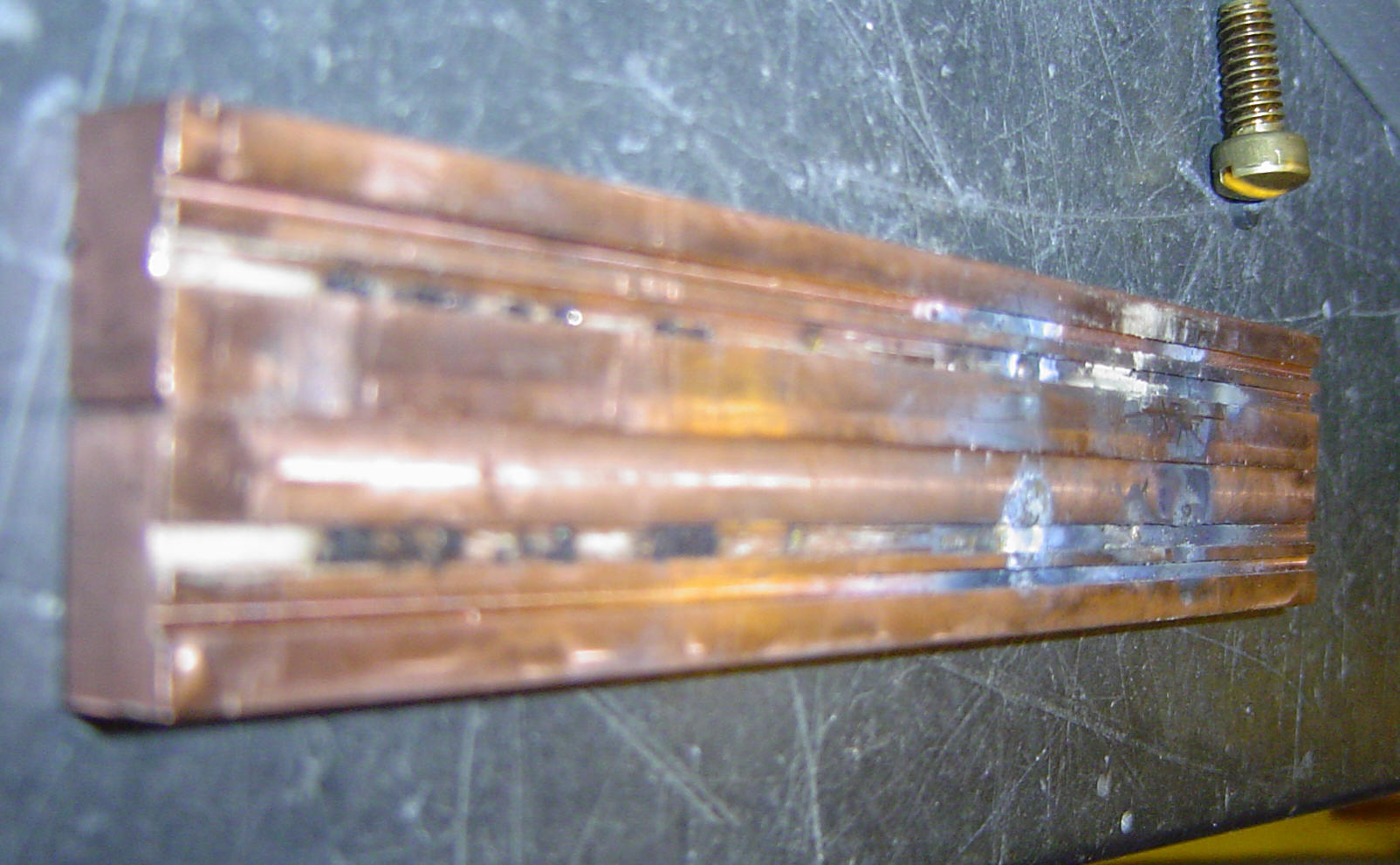
we began with 1 completely misshapen rectangle and worked quite hard to make it into 2 identically-sized rectangular prisms. (and we failed)
-they were 6 inches in length, .510 inches in height, and .370 inches in width each. We initially planned a 62.5 mils groove, but accidentally milled a 87.5 mil groove, which actually turned out to be better because the rails weren't properly lined up and an armature would not have fit in a smaller groove.
- accuracy of cutting:
-for the copper we first made two rails, then put them side by side in the vice and cut the grooves parallel (or so we thought-- the very small impression of the rails relative to the grooves made the grooves not parallel once the rails were screwed to the g-10)
Power equipment:
Our 100-amp supply (which made tons of noise because of the broken fan or something):

Firing the copper Rails:
We fired the copper rails, but the firing melted the brass armature. You can see in the copper rail photo above the spots that the melting left.
at that point we realized we need armatures that didn't melt, and under Romalis's guidance we made graphite armatures:
for the armatures we narrowed a cylinder of graphite down to 182 mils in diameter, and then sliced it into disks of 63 mils height. (slices of width 63 if you think of it as salami). the grooves were 37 mills deep, so we placed the rails 108 mils apart.
Still, we could not get significant firing, mostly because our two bars were at a different angle so the surface of contact on which the armature was supposed to rest was not smooth so it had poor conductance, and also melted the copper bars as seen and discussed above.
So the copper bars were ruined and we were dejected and decided we had to make graphite rails.
Machining graphite rails:
-for the graphite we began with a 2-inch diameter cylinder that was 24 inches long.
we cut it in half with a band saw to make it 2x12, cut that in half with a band saw to make it a semicircle. flattened out the new flat front of the semi-circle with a mill. machined off (with a mill) the top and bottom of the semi circle (look at the pic above). then put that whole long semicircle with the long flat face up and cut the groove in two cuts with a 1/16 end mill, making the groove 87.5 mils wide.
then we cut (with a band saw) the 12 inch beast in half to produce a standard quality 6-inch penis. we milled off the tips (the things facing you in the pic) and then drilled a hole into each (3/16s in radius) and threaded them and put in the screws you see in the photo.
finally, along the top we drilled 4 holes each for a screw of size 6-32. finally, we cut a rectangular platform out of g-10 (wearing a safety mask, of course!) and drilled room for the 4 vertical screws. we put the screws through and held them with nuts, because none of these 4 holes were threaded.
graphite cuts much easier than copper and you can go much faster w/o having to worry about damaging the end-mills and your piece. The only difficulty to cutting graphite is that it is chippable and a quick exit will chip your piece.
also, it dirtied whole room.
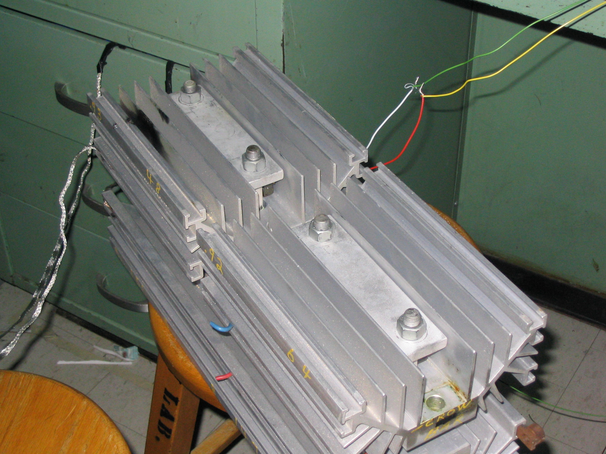
Power equipment II (the capacitors):
In preparation for the graphite rails actually working we procured capacitors and a power source with which to charge them, and a switch designed for high voltages and current with which to set off the apparatus from a distance.
 |
 |
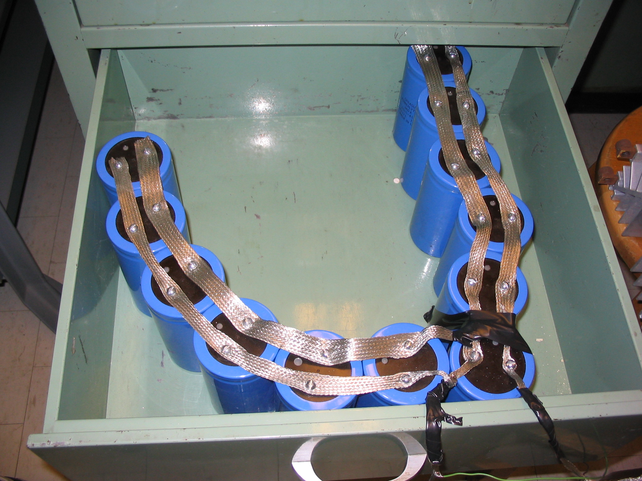 |
| (the capacitor charger) | (the switch) | (capacitors) |
Firing the graphite rails
![]()

First we fired with the steady power supply which we had used on the copper bars.
Here is the movie: MOV01229.MPG
To test that they were going far we put a barrier
Successfully firing the graphite rails: railgun.avi
Results:
We put a barrier 24 ft away and it went over it, giving it a min speed of about 70 ft/s. However, we think it hit the wall at a height of 15 inches, giving it a speed of 140 ft/s.
The rail gun was fired from a height of 25 inches with an angle of 1/10 inch / 6 inches so ~1 degree