Princeton Gas Dynamics Lab Facilities
Here is a list of the main facilities at the Gas Dynamics Lab:
Return to Gasdynamics Home Page.
The Hypersonic Boundary Layer Facility
The HyperBLaF is a Mach 8 blowdown wind tunnel used for fundamental studies of compressible turbulence, shock wave/boundary layer interactions, shock/shock interactions and configuration studies of hypersonic vehicles. The working section is circular, with a diameter of 229mm (9"), with an overall length of 2.0m (6 ft). A maximum stagnation temperature of 870K (1100F) at a maximum stagnation pressure of 10 MPa (1500 psia) is possible; run times will vary from approximately 2 to 10 minutes. The tunnel operating conditions were chosen to give a Reynolds number range so that at the lowest Reynolds number the flow will be laminar (even on the tunnel walls), and at the highest Reynolds number fully turbulent boundary layers will be generated on a flat plate mounted in the test section. Even at Mach 8 a Reynolds number based on momentum thickness of about 15,000 seems possible, with natural transition and a highly cooled wall. The key part of the installation is a storage heater which consists of a coil or array of heavy walled stainless steel pipe which is preheated electrically to the desired stagnation temperature, so that the pipe stores the heat and contains the high pressure gas. The vacuum system uses an air ejector driven by the existing high pressure air supply to provide low back pressures. The tunnel can be operated with air or other gases (the mass flow rates are relatively small).The tunnel is approximately 30 ft (9 m) long, not including the assembly used to heat the incoming flow. The high pressure air supply is connected to the inlet of the heater assembly by a valve which expands the air from 3000 psi (20 MPa) to 1500 psi (maximum) through 250 psi (minimum) depending on the Reynolds number desired. After being heated, the air passes into the flow conditioning section and is then expanded through the nozzle. The flow properties remain approximately constant through the test section at the design Mach number of 8 until reaching the diffuser. At the diffuser inlet, the flow accelerates briefly before being compressed through a complicated shock system (there is no second throat) and then cooled to approximately ambient temperature in the heat exchanger. It then passes through the ejector system before exiting via a silencer outside. The inlet flow conditions are limited by the maximum pressure and temperature specified in the design of the heater assembly. The capacity of the air storage facility limits possible run times due to the large mass flow demands of the ejectors.
A high-strength material was needed to withstand the combination of high stagnation temperatures and pressures in the upstream sections of the facility. Inconel was considered, but 316L stainless steel was selected as the fabrication material because of its relatively low cost in comparison with Inconel. 316L stainless is a material used in high-temperature applications. It is readily available and has good strength and corrosion properties. 316L was used to fabricate the heater coil, nozzle, test section, expansion joint, and diffuser.
Pictures
Figure 1. Schematic of the Hypersonic Facility
Click to see larger photo (63k)
Figure 2. Schlieren Photo of Flat Plate Model taken in the Facility
The Supersonic Combustion Facility
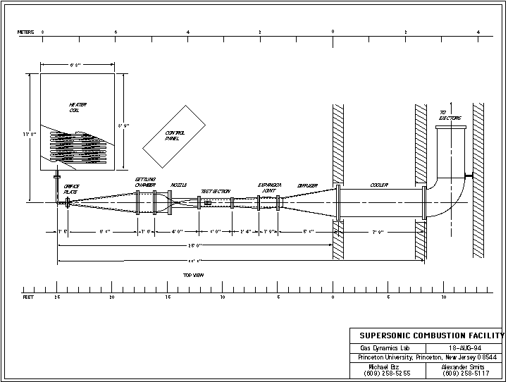
The high pressure air system and the new heater built as part of the hypersonic boundary layer facility will provide a source of clean, high temperature, high pressure air for the combustion facility. By building a new settling chamber, nozzle and working section, we will have the additional capability to perform supersonic combustion experiments in two and three-dimensional turbulent flows at static pressures up to 0.4 atmospheres, static temperatures of 300K, with flow run times up to 30 seconds. We have made considerable progress in the design of this facility, but construction is on hold due to lack of funding.
Schematic of the Supersonic Combustion Facility
The 8" x 8" Supersonic Wind Tunnel
The 8 x 8 facility is an aptly-named 200mm x 200mm high Reynolds number supersonic blowdown facility, equipped with Mach 2 and Mach 3 nozzles. The tunnel is composed of three interchangeable test sections, and a number of special-purpose sections are available. This facility is extremely flexible, in that a large number of different configurations can be tested with relative ease. It is suitable for testing over a wide range of Reynolds numbers, and models can be mounted on the floor, on a false plate, or on a sting. Optical access is through two 8" diameter schlieren windows, and their location is variable by changing the section location and orientation. Surveys can be made in the transverse and longitudinal directions, and an eccentric window arrangement allows detailed examination of three-dimensional flows. The facility is supported by Schlieren and shadowgraph systems, one- and two-component automated traverse systems, automated scanivalve pressure survey equipment, eight channels of high-frequency pressure transducers and six channels of constant-temperature anemometer equipment.The LTVG Facility
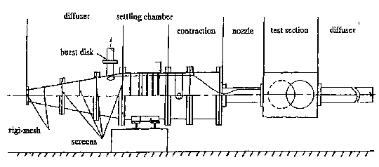
The 200mm x 300mm Low-Turbulence Variable Geometry (LTVG) Supersonic Wind Tunnel is equipped with Mach 2 and Mach 3 nozzles. The facility was designed to fulfill three specific objectives: l) Low turbulence levels in the flow upstream of the throat. The design of the entrance cone, settling chamber and contraction was based on the experience developed by Bushnell and Beck with in the design of "quiet" supersonic tunnels at NASA-Langley Research Center; 2) Studies of boundary layer relaxation following strong flow deflections. For example, with an upstream Mach number of 3, the boundary layer relaxation following a 24 degree compression corner can be studied up to 50 initial boundary layer thicknesses downstream of the interaction; 3) Generous optical access. The working sections are being modified to accept 24" diameter optical windows to permit wide-field flow visualization and the use of optical probes. The tunnel is connected to the ejector system so that back pressures as low as 0.5 psia are possible. Therefore the tunnel can be operated at very low Reynolds numbers to study transition and transition control at Mach numbers of 3 and 5, and at very high Reynolds numbers representative of flight Reynolds numbers (up to 10e8/m).

Schematic of the LTVG Facility
The SuperPipe Facility
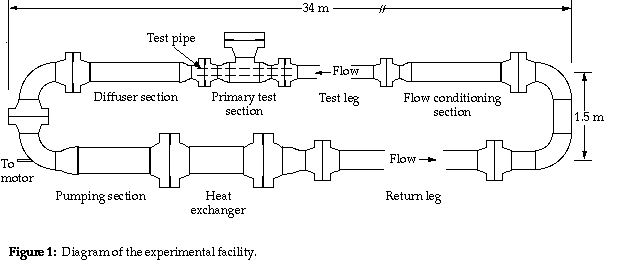
An experimental facility has been constructed to investigate a fully developed turbulent pipe flow over a large range of Reynolds numbers. This wind tunnel is called the Princeton/DARPA-ONR SuperPip Facility, and it uses air at pressures up to 3,500psi as the working fluid In the past many experiments (Nikuradse, 1932; Laufer, 1954 and Townes et al., 1972 to name a few) have been performed on a fully developed turbulent pipe flow because of its simplicity and industrial importance. However, despite the vast amount of data in publication it is difficult to find satisfactory agreement (on friction factor and turbulence intensities for example) between investigations or to find data at very high Reynolds numbers where many industrial systems operate. All of these investigations are lacking in some respect due to either a limited range of Reynolds numbers investigated, an uncertainty in the quality of the inner pipe finish, a questionable accuracy of the measurements, or a lack of experimental proof that the turbulence is fully developed. In the design of the Superpipe, particular attention was paid to the question of obtaining fully-developed flow (L/D = 200, with an internal diameter of 5.09in), and achieving a smooth-wall finish (roughness < 6 microin). Therefore, we believe that the Superpipe allows very accurate measurements over a large range of Reynolds numbers, from approximately 5,000, to more than 38,000,000, corresponding to an order of magnitude increase over the highest Reynolds number for mean flow measurements (Nikuradse, 1932), and almost two orders of magnitude over the highest Reynolds number for turbulence measurements (Townes et al., 1972).Results have led to a new set of scaling laws for turbulent pipe flow, showing that the almost universally accepted logarithmic behavior does not hold in the near-wall region. There, a power law holds instead, and a logarithmic behavior appears only at Reynolds numbers that are considerably greater than those commonly achieved in the laboratory. The scaling has been extended to boundary layer flows, and comparisons with existing data are very encouraging. The original mean flow data set is available here, and further details of the facility are given by Zagarola (1996). This work is ongoing, as are detailed studies of the turbulence behavior, which are focusing on the extension of these scaling laws to the turbulence behavior. This work is currently supported under ONR Grant N00014-97-I-0618 "Student Training Program in the Study of High Reynolds Number Turbulent Flows."
Relevant Publications

Schematic of the SuperPipe Facility
The SuperTunnel: a High Reynolds number Test Facility (HRTF)
The Superpipe experiment demonstrated the success of high-pressure air as a working fluid to attain very high Reynolds numbers cost-effectively. In 1998, an ONR-DURIP grant (N00014-98-I-0325) was awarded to construct a wind tunnel based on the same principle. This wind tunnel is called the Princeton/ONR High Reynolds Number Testing Facility -- HRTF, and like the Superpipe it uses air at pressures up to 3,500psi as the working fluid. The primary purpose of the new facility is to study the hydrodynamic forces, moments and flow-fields produced by submarine shapes up to length Reynolds numbers of 175 x 106 (approximately 1/5th full-scale). There are two working sections: each is 8ft long with an internal diameter of 18in. The facility will be equipped with a Magnetic Suspension Balance (MSB) to allow measurements free of the interference produced by the support systems usually employed in these applications. The new facility is currently (Spring of 2000) available for new experiments (without MSB). The MSB will be designed, constructed and tested under the supervision of Colin Britcher of ODU. We anticipate that the MSB is expected to be ready for full-scale testing in December 2000. See for more details.
Relevant Publications
Schematic of the SuperTunnel Facility
The Gas Dynamics Water Channel Facility
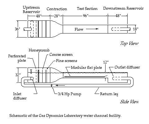
The Gas Dynamics Laboratory Water Channel is a closed circuit, free-surface facility. It was originally designed to study the effect of long-chain polymers on the transition to turbulence. Lately, it has been used to collect long time series volumetric data sets. The object of this research is to study the role of coherent structures in a low Reynolds number turbulent boundary layer. A detail of the modular flat plate is available. If you would like to see some examples of data sets which were obtained in this facility, you may go to the Stereoscopic Visualization menu:Schematic of water channel facility.
Taylor-Couette Flow Apparatus
This section is still under construction. For more info contact Arel Weisberg
To learn more about Taylor-Couette flow click here
To learn more about research in Taylor-Couette flow phenomena going on at the Gas Dynamics Lab click here.
Air System
This section is under construction.Return to Gasdynamics Home Page.
