Next: Spring Elements Up: Model Definition Previous: Slide Lines
![]()
![]()
![]()
![]()
Next: Spring Elements
Up: Model Definition
Previous: Slide Lines
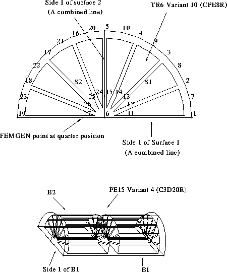
The interface provides two degenerate element variants which are commonly used at crack tips; the CPE8R (modelled as a TR6 in FEMGEN) and the C3D20R (modelled as a PE15 in FEMGEN). Note that non-degenerate versions of these elements are also available as QU8's and HE20's.
In 2D the user must ensure that each surface is correctly oriented in order to degenerate the desired side of the CPE8R. Side 1 of the surface(s) should be as illustrated below. Any number of divisions are allowed along side 2 but there must only be 2 divisions on sides 1 and 3. Sides 1 and 3 can then be split and the resulting geometric point used to control the mid-side node positions. Similar rules apply in 3D for C3D20R elements.
Pressure, hydrostatic and heat loads should not be applied to the degenerate sides of these elements.