| |
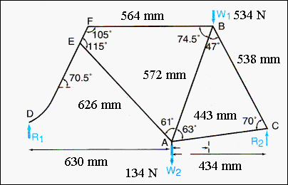
The diagram
shows typical dimensions and angles associated with a touring bicycle
frame. W1
and W2
show the forces on the seat and the pedals due to a rider and R1 and
R2
are the forces acting on the frame due to the reaction forces at the
wheel axles. The bicycle must be in equilibrium under the action of these forces,
and that requires that there are no net forces or moments acting on it.
All
forces are "vertical" and force balance gives: (W1 + W2)
= (R1 + R2) = 668 N.
Moments can be taken about
any point, and selecting the front axle (D) gives:
|
|
|
|
|
|
|
|
|
|
|
|
|