|
The
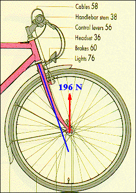
front fork is another component that experiences an off-axis force and
hence a bending moment. The diagram shows the force at the wheel axle for
a statically loaded bike and this makes an angle of approximately 19.50
with the centerline of the front fork (blue line). the force can
be resolved into a component along the tube, FP
= 196 cos(19.5) = 185 N, and a force normal
to the tube, FN = 196 sin(19.5)
= 65.4 N. The parallel force puts the tube
in compression, the normal force gives rise to a bending moment that has
its maximum value at the bottom head-set bearing.
If
the fork is approximated by a straight beam of uniform cross-section that
has a length of 480 mm, the bending moment increases linearly from zero
at the axle to a value of:
M = 0.480 FN N.m = 31.4 N.m
at the bearing. The maximum stress in the tubes of the fork is given by
smax
= 0.5(MD/2I),
where the factor of 0.5 is due to there being two tubes and D/2 is the
maximum distance of tube material from the neutral axis (blue line). Using
an elliptical tube of 1.34 mm wall thickness and diameters of 31.8 and
19 mm gives a moment of inertia of 1.53 x
10-8 m4, and a maximum
stress value of 16.3
MPa, i.e. (smax/sy)
= (16.3/180) = 9 x 10⁻². |
|
|
|
|
|
|
|
|
|
|
|
