Next: GEOMETRY SURFACE SIDE-PNT [snam] lnam pnam Up: GEOMETRY SURFACE Control Previous: GEOMETRY SURFACE ONSHAPE shnam angval
![]()
![]()
![]()
![]()
![]()
Next: GEOMETRY SURFACE SIDE-PNT [snam] lnam pnam
Up: GEOMETRY SURFACE Control
Previous: GEOMETRY SURFACE ONSHAPE shnam angval
This command is used to create a multiple sided surface with optional internal holes.
| snam | = | name of the surface, used for later references to the surface. |
| set_outer | = | name of a set containing a list of lines forming a closed loop. |
| set_inner* | = | set names containing a list of lines forming closed loops which represent |
| the internal holes. One set per hole. | ||
| elt | = | element type on the surface. A default element type of QU4 will be |
| assumed if `elt' is not given. Refer to command | ||
| MESHING TYPES for a detailed description. |
In order that a region can be defined a set must exist which contains lines forming a closed loop representing the outer boundary of the region. The lines can be appended to the set in any order.
Internal holes are also defined using sets of lines, with a set containing a closed loop for each hole. Holes may be given in the initial definition of the region as well as added or removed once the region is defined (with the GEOMETRY SURFACE REGION snam APPEND/REMOVE command). Whenever a region is modified the existing mesh will be cancelled. Internal holes must be within the external boundary.
Regions can be mixed with 3 and 4 sided FEMGEN surfaces. Mesh density is controlled by the divisions on the lines defining the region, thus ensuring continuity of mesh between surfaces.
Unlike 3 or 4 sided surfaces the internal shape is not derived from the external boundary; consequently a FEMGEN shape must be assigned to the surface unless it is planar. The MESHING SHAPE command is used to assign a shape to a surface.
Notes:
Return Level: GEOMETRY SURFACE
Examples:
Create a multiple sided surface S25 from the lines forming a closed loop that are in the set OUTER.
Add the holes defined by the lines in the sets HOLE1, HOLE2 and HOLE3 to the existing definition of S25.
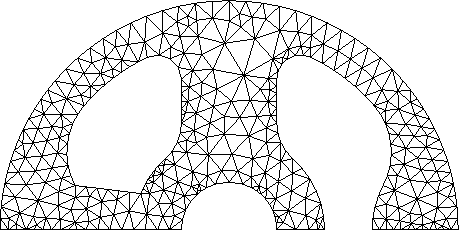
Create a multiple sided surface from the lines forming a closed loop that are in the set OUTER, with three internal holes defined by the sets HOLE1, HOLE2 and HOLE3. The surface name will be generated automatically by FEMGEN. The surface definition will be similar to the resulting surface shown in example 1 and 2.
An example mesh on such a region is shown below.
Remove the hole defined by the set HOLE2 from the definition of the surface COVER.
See also the following commands
'LABEL GEOMETRY SURFACES'
'CONSTRUCT SET '
'MESHING DIVISIONS'
'MESHING GENERATE'
'MESHING SHAPE'
'UTILITY DELETE SURFACES'
'UTILITY TABULATE GEOMETRY SURFACES'
'VIEW GEOMETRY'
Femsys Limited